STM 32 Input Capture(超音波センサ)を使用
71253 ワード
緒論
マザーボード:F 429 ZI
IDE : Keil MDK-ARM
Input Capture
受信した信号をキャプチャします.
それは何ですか.
アドゥエノを思うと.
既存のInputは、サイクル中に所定の間隔の信号を受信する.
しかし、それは私が自分で計算するタイミングをつかまえなければなりません.
別の入力方法でボタンを中断すると、
あなたが望むときに信号を受け取ることができます.
ただし、結果値を知るにはmillis()関数を使用して計算する必要があります.
では、必要なときに一定のルールを持つ信号を受け取り、結果を知りたい場合は、どうすればいいのでしょうか.
それは.
指定した間隔を[基点](Timer)として比較します.
計算値を付けずに、受信した信号から結果を知るしかありません.
すなわち,信号の周波数とデューティはTimerで得ることができる.
これらのInput Capture機能をよりよく見るために、
超音波センサーはあなたにぴったりです.
入手しやすい
HC-SR 04を使用します.
超音波センサー
超音波センサはTriggerを介して信号を出力する
エコーに反射して信号を受信する
高い測定時間を算出する.
距離を把握するセンサーです.

まず、HC-SR 04超音波センサに
▶動作頻度
超音波センサーは40 Hz.
信号は40 Hzより遅いはずです.
これは最大距離4 mに関係している.
音速:340 m/s
往復距離:4 m+4 m=8 m
距離=時間x速度
時間=距離/速度
最大距離往復時間=8 m/(340 m/s)->計算しにくい(約0.0235 s=23 ms)
最小距離往復時間=0.04 m/(340 m/秒)=0.0001764秒=約117秒
周波数=1/時間=(340 m/s)/8 m=42.5 Hz
という結果に.
つまり、往復に要する最大時間
40Hz = 0.025 s = 25ms
そのため、この時間よりも早く(より大きな周波数)繰り返すと
つまり、センサーが認識できない.
これはステッピングモータの周波数とは意味が異なる.
ステッピングモータは、所定の周波数でのみPWMを用いてデューティ比を調整することができる.
を選択して設定できます.
▶トリガ入力信号
Trigger端に10 usのTTLパルスを出力します.
出力40 kHzの超音波は8回発生する.
TTL : Transistor-transistor logic
トランジスタ付きNANDなどの論理回路

測定時間は一番下の赤い四角い部分です.
測定時間(秒)/58 -> cm
測定時間(秒)/148->インチ
距離=時間x速度
速度=音の速度(340 m/s)/2
最小測定サイクルは0.06秒(60ミリ秒)<−25ミリ秒と計算した.
一般的には、0.1秒を基準によく測定されます.
CubeMx設定
1. TIM3 - Input Capture
Input Captureを使用するTIM 3の場合:
TIM 3サイクルでリング(CH 1)とリング(CH 1)を測定すると、
値はCRxレジスタに書き込まれます.
CRx値の間隔で周期を知ることができます.
正確に測定するために
Prescaler
Period
値段を正さなければならない.
▶プリディビジョンが小さければ
周波数(f)が大きい
->ライフサイクル(T)が短い
->タイマー加速
->Counter Periodも小さくできたら
->過剰updataイベントの発生
->Expired(期限切れ)クロックオカレンス
->測定センサーや機器のライフサイクルの特定が困難
▶プリディビジョンが大きいほど
忙しいクロック周波数が小さくなるため(クロック時間を1つ延長)
ばかにして見る
->精度が落ちる.
測定するセンサの最小単位を取得する必要があります.
所要時間:1 us=1 MHz
TIM3 => APB1 Timer = 90MHz
プリスプリッタ=90(入力:90-1)
超音波は0.1 s毎に送信される.
Input captureが発生した時間はその内部にある.
超音波の一周期より大きくさえあれば,Input Capture値を良く測定できた.
ただし、TIM 3は16ビットタイマーです.
最大Counter Period値は2^16=65536(0~65535)
着くしかない.
Counter Period = 65535
つまり、Input Captureのタイマーカウンタが回転します.
RisingとFallingを測定した.
DMAに保存する場合
CPUクロックなしでデータを取得できます.
RisingとFallingを測定するInput Capture Directモードを選択します.

割り込みを有効にします.

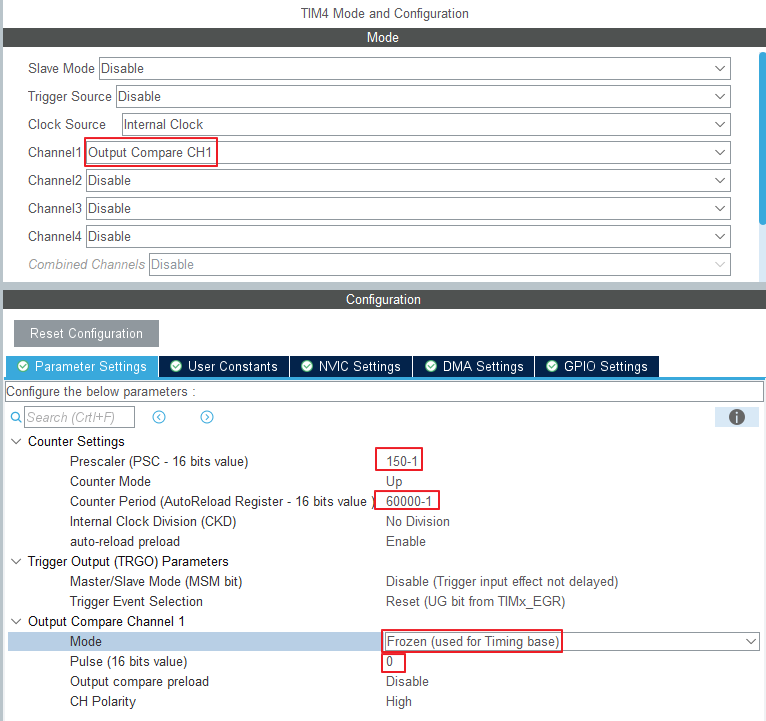
2. TIM4 - Trigger Output
超音波を制御するためのTriggerのTimer.
mainに入れると遅延時間が発生するので、それをTimerに分離したい.
必要に応じて出力信号を出力ために、
Timer - Output Compare - Frozen Mode
に設定します.
方法
Counter Period値を設定し、Overflowを作成します.
PeriodEducedCallback関数の内部
Delay us関数の作成による10 usの作成
Timer時間=超音波時間
方法
脈拍を調節する
サイクル失効callback関数->Trigger:HIGH
DelayDelivedCallback関数 -> Trigger : LOW
HIGH-LOW時間間隔=10 us
Timer時間=超音波繰返し時間

System Clock = 180MHz
APB1 Timer = 90MHz
所要時間間隔=0.1 s
Prescaler=150->(150-1:0~149=>150)
分=900000 Hz/150=600000 Hz=600 kHz
Counter Period = 60000 (60000 -1)
Result = 600kHz/60000 = 10Hz => 0.1s
サイクル失効callback関数は0.1 sごとに実行されます.
方法を考える
ここで一番下が0のパルス(16ビット値)を設定すればよい.
Pulse->CCR値(カウント期間の1時間間隔)
所要時間間隔=10 us
0.1s -> 60000
0.00001s -> ?
Pulse = (0.00001s x 60000)/0.1s = 6
1 usあたり0.6パルス増加
入力:6-1=5
11 us=6.6-1=>約6入力
=>2法は100 msと10 usの時間間隔が大きすぎて測定が困難である.
もちろん、間近で見るとよく測れます.10 usより小さいのでPulseは7くらいで大丈夫です

auto-reload preload => Enable
ピンの設定
PA6 -> TIM3_CH1
PC7 -> TIM3_CH2
PB6 -> GPIO_OUTPUT (LABEL : TRIGGER)
プロジェクトの作成
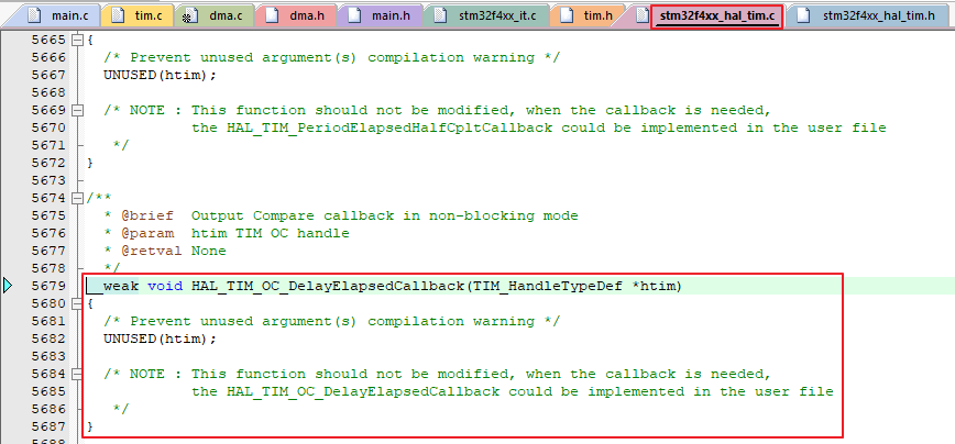
Timer関数
私たちが探しているほとんどの機能はHALドライバの中にあるので、よく探してみましょう.


上に述べたように.
HAL TIM PeriodEducedCallbackカウントサイクルを超えるオーバーフローが発生した場合
呼んでください.
HAL TIM OC DelayDelivedCallbackは、パルスによって指定されたCCR値に達したときにロードされる.
タイマーを起動するには
HAL TIM Base Start IT(&タイマー使用);
Output Compare Calback関数を使用するには
HAL TIM OC Start IT(&タイマー、チャネル使用);
どうしても入れなければならない.HAL_TIM_Base_Start_IT(&htim4);
HAL_TIM_OC_Start_IT(&htim4, TIM_CHANNEL_1);
この方式は方法2に相当する.
PeriodElapsedCallback -> 10ms
OC_DelayElapsedCallback -> 10usvoid HAL_TIM_PeriodElapsedCallback(TIM_HandleTypeDef *htim)
{
GPIOB->ODR |= 0x01 << 6; // PB6 Trigger SET
}
void HAL_TIM_OC_DelayElapsedCallback(TIM_HandleTypeDef *htim)
{
GPIOB->ODR &= ~(0x01 << 6); // PB6 Trigger RESET
}
Delay_us
通常のHAL Delay()がミリ秒単位であれば
DWT Delay us()関数はusに入力できます.uint32_t DWT_Delay_Init(void)
{
/* Disable TRC */
CoreDebug->DEMCR &= ~CoreDebug_DEMCR_TRCENA_Msk; // ~0x01000000;
/* Enable TRC */
CoreDebug->DEMCR |= CoreDebug_DEMCR_TRCENA_Msk; // 0x01000000;
/* Disable clock cycle counter */
DWT->CTRL &= ~DWT_CTRL_CYCCNTENA_Msk; //~0x00000001;
/* Enable clock cycle counter */
DWT->CTRL |= DWT_CTRL_CYCCNTENA_Msk; //0x00000001;
/* Reset the clock cycle counter value */
DWT->CYCCNT = 0;
/* 3 NO OPERATION instructions */
__ASM volatile ("NOP");
__ASM volatile ("NOP");
__ASM volatile ("NOP");
/* Check if clock cycle counter has started */
if(DWT->CYCCNT)
{
return 0; /*clock cycle counter started*/
}
else
{
return 1; /*clock cycle counter not started*/
}
}
void DWT_Delay_us(volatile uint32_t microseconds)
{
uint32_t clk_cycle_start = DWT->CYCCNT;
/* Go to number of cycles for system */
microseconds *= (HAL_RCC_GetHCLKFreq() / 1000000);
/* Delay till end */
while ((DWT->CYCCNT - clk_cycle_start) < microseconds);
}
Delayとタイマーで0.1秒ごとに10 usパルスを出力します.
方法1.void HAL_TIM_PeriodElapsedCallback(TIM_HandleTypeDef *htim)
{
/* when TIM3 got Update Event */
if(htim->Instance == TIM3){
GPIOB->ODR |= 0x01 << 6; // PB6 Trigger SET
DWT_Delay_us(11);
GPIOB->ODR &= ~(0x01 << 6); // PB6 Trigger RESET
}
}
超音波が正常に生成されれば.
Echoピンでは、距離に応じて信号が発生します.

Input Capture
この関数では、取得したCCR値を取得できます.HAL_TIM_ReadCapturedValue(htim, TIM_CHANNEL_1);
周波数を計算するときはこの表を見ます.
PCLK1 = APB1 peripheral Clock = 45MHz -> HAL_RCC_GetPCLK1Freq( )
PSC = Prescaler

関連計算コードfreq = (HAL_RCC_GetPCLK1Freq()*2)/(htim3.Instance->PSC + 1); // (45MHz*2) / 90 = 1MHz = 1,000,000 Hz
コード#コード#
コードを説明する手順は、次のとおりです.

タイマーが信号の中でどのように位置決めされているかを知る必要があります.
RISING Edge
Rising Code部分/* Rising */
if(htim->Instance == TIM3 && htim->Channel == HAL_TIM_ACTIVE_CHANNEL_1)
{
// Rising CCR 값 읽어오기
risingCapture[risingCNT] = HAL_TIM_ReadCapturedValue(htim, TIM_CHANNEL_1);
if(risingCNT == 1){
risingCNT = 0;
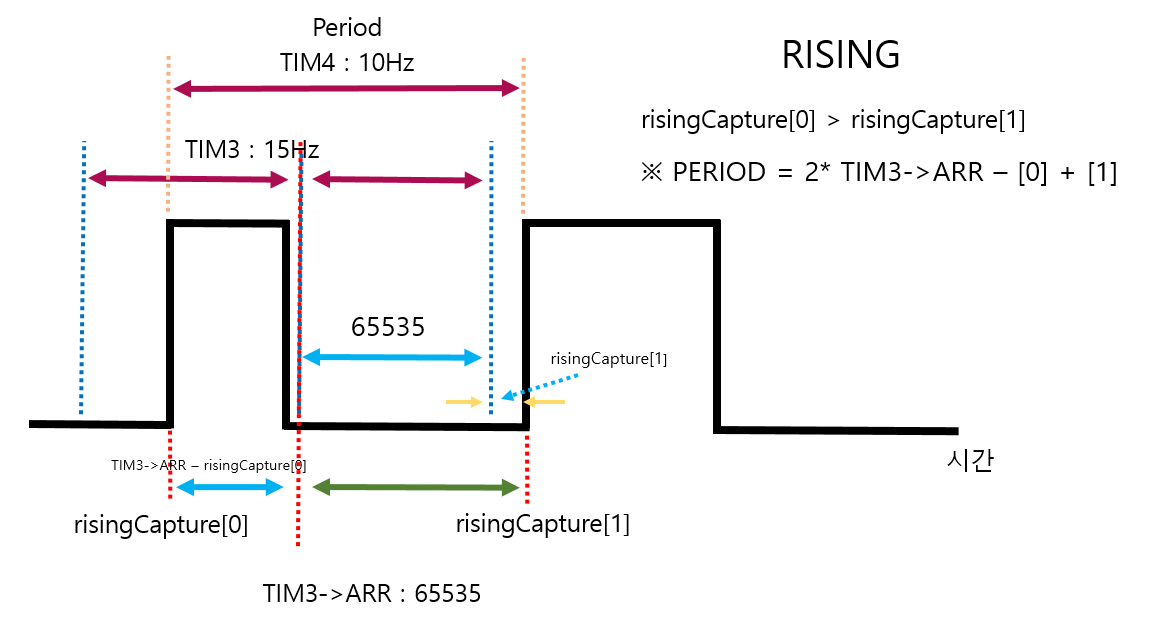
if(risingCapture[0] > risingCapture[1])
{
period = TIM3->ARR - risingCapture[0] + risingCapture[1];
GPIOB->ODR |= LD3_Pin;
}
else
{
period = risingCapture[1] - risingCapture[0];
}
period += TIM3->ARR; // 65535 + 34000 => sonar PSC 150 rising PSC 90
}
else
{
risingCNT = 1;
GPIOB->ODR &= ~LD3_Pin;
}
GPIOB->ODR |= LD1_Pin;
GPIOB->ODR &= ~LD2_Pin;
freq = (HAL_RCC_GetPCLK1Freq()*2)/(htim3.Instance->PSC + 1); // (45MHz*2) / 90 = 1MHz = 1,000,000 Hz
freq = freq/period;
}
if(risingCNT == 1)
配列に0,1インデックスを配置します.
1の場合、無条件で0 1の順にリストされます.
通常、TIM 3は、TIM 4未満の周波数(長周期)で広いInput Captureを行う.
1 us単位で
Prescalerの縮小
最大65535のComputer Period(16ビット)を入力します.
約15 Hzです.
だから次のように二つに分けました.
いつものようにTIM 3 Hz上のifドアを除いて、同じように使用されています.ピクチャで拡大

これは赤い破線が要求する周期間隔です.
青い点線はTIM 3の間隔です.
黄色の点線はTIM 4の間隔です.

最初のif文では、タイマ3号のchannel 1がRisingを認識するとアクティブになります.if(htim->Instance == TIM3 && htim->Channel == HAL_TIM_ACTIVE_CHANNEL_1)
TIM 3->ARR=65535のオーバーラップ部分は次のように処理されています.period += TIM3->ARR; // 65535 + 34000 => sonar PSC 150 rising PSC 90
周波数は、TimerのCounter Periodを計算するように、Prescalerで計算した周波数をPeriod値で除算すればよい.freq = (HAL_RCC_GetPCLK1Freq()*2)/(htim3.Instance->PSC + 1); // (45MHz*2) / 90 = 1MHz = 1,000,000 Hz
freq = freq/period;
FALLING Edge
/* Falling */
if(htim->Instance == TIM3 && htim->Channel == HAL_TIM_ACTIVE_CHANNEL_2)
{
// Falling CCR 값 읽어오기
fallingCapture[fallingCNT] = HAL_TIM_ReadCapturedValue(htim, TIM_CHANNEL_2);
if(fallingCNT == 1){
fallingCNT = 0;
}else{
fallingCNT = 1;
}
if(fallingCapture[0] >= risingCapture[0] && fallingCapture[0] <= risingCapture[1])
{
width = fallingCapture[0] - risingCapture[0];
}
else if(fallingCapture[1] >= risingCapture[0] && fallingCapture[1] <= risingCapture[1])
{
width = fallingCapture[1] - risingCapture[0];
}
GPIOB->ODR &= ~LD1_Pin;
GPIOB->ODR |= LD2_Pin;
distance = width / 58;
if(distance > 400) distance = 400;
duty = width * 100/period;
}
TIM 3のチャンネル2でfallをキャプチャすると、CCR値が保存されます.fallingCapture[fallingCNT] = HAL_TIM_ReadCapturedValue(htim, TIM_CHANNEL_2);
つまり、それぞれ下降と上昇が交差することになる.
よく見るとrisingCapture[0]とrisingCapture[1]は変わっていません.
fallingCapture[0]とfallingCapture[1]のみが変更された.
要するに、最初のrippingを検出し、fallが0なのか1なのかを検出します.if(fallingCapture[0] >= risingCapture[0] && fallingCapture[0] <= risingCapture[1])
{
width = fallingCapture[0] - risingCapture[0];
}
else if(fallingCapture[1] >= risingCapture[0] && fallingCapture[1] <= risingCapture[1])
{
width = fallingCapture[1] - risingCapture[0];
}
Full Code
/* USER CODE END Header */
/* Includes ------------------------------------------------------------------*/
#include "main.h"
#include "tim.h"
#include "usart.h"
#include "gpio.h"
/* Private includes ----------------------------------------------------------*/
/* USER CODE BEGIN Includes */
#include "stdio.h" // printf
#include "stdbool.h" // true, false
/* USER CODE END Includes */
/* Private typedef -----------------------------------------------------------*/
/* USER CODE BEGIN PTD */
/* USER CODE END PTD */
/* Private define ------------------------------------------------------------*/
/* USER CODE BEGIN PD */
/* USER CODE END PD */
/* Private macro -------------------------------------------------------------*/
/* USER CODE BEGIN PM */
/* USER CODE END PM */
/* Private variables ---------------------------------------------------------*/
/* USER CODE BEGIN PV */
volatile uint16_t risingCapture[2];
volatile uint16_t fallingCapture[2];
uint8_t risingCNT = 0;
uint8_t fallingCNT = 0;
uint32_t period, freq, duty;
uint16_t width, distance;
// Printf 사용을 위한 더미 파일
struct __FILE {
int dummy;
};
FILE __stdout;
/* USER CODE END PV */
/* Private function prototypes -----------------------------------------------*/
void SystemClock_Config(void);
/* USER CODE BEGIN PFP */
int fputc(int ch, FILE *f)
{
HAL_UART_Transmit(&huart3, (uint8_t *)&ch, 1, 0xFFFF);
return ch;
}
/* 마이크로세컨드 함수 선언 */
uint32_t DWT_Delay_Init(void);
void DWT_Delay_us(volatile uint32_t microseconds);
void TriggerEnable(void);
/* USER CODE END PFP */
/* Private user code ---------------------------------------------------------*/
/* USER CODE BEGIN 0 */
/* USER CODE END 0 */
/**
* @brief The application entry point.
* @retval int
*/
int main(void)
{
/* USER CODE BEGIN 1 */
/* USER CODE END 1 */
/* MCU Configuration--------------------------------------------------------*/
/* Reset of all peripherals, Initializes the Flash interface and the Systick. */
HAL_Init();
/* USER CODE BEGIN Init */
/* USER CODE END Init */
/* Configure the system clock */
SystemClock_Config();
/* USER CODE BEGIN SysInit */
/* USER CODE END SysInit */
/* Initialize all configured peripherals */
MX_GPIO_Init();
MX_TIM3_Init();
MX_TIM4_Init();
MX_USART3_UART_Init();
/* USER CODE BEGIN 2 */
// timer, channel, array, quantity
DWT_Delay_Init();
// HAL_TIM_PeriodElapsedCallback
HAL_TIM_Base_Start_IT(&htim4);
// HAL_TIM_OC_DelayElapsedCallback
HAL_TIM_OC_Start_IT(&htim4, TIM_CHANNEL_1); // create Sonar
// HAL_TIM_IC_CaptureCallback
HAL_TIM_IC_Start_IT(&htim3, TIM_CHANNEL_1); // rising
HAL_TIM_IC_Start_IT(&htim3, TIM_CHANNEL_2); // falling
printf("start the program\r\n");
HAL_Delay(2000);
/* USER CODE END 2 */
/* Infinite loop */
/* USER CODE BEGIN WHILE */
while (1)
{
HAL_Delay(100);
printf("[%5d, %5d]-%5d = %5d => Distance %4d cm| period : %6d | freq : %3d Hz| duty : %d %%\r\n", risingCapture[0], risingCapture[1], fallingCapture[0], width ,distance, period , freq, duty);
/* USER CODE END WHILE */
/* USER CODE BEGIN 3 */
}
/* USER CODE END 3 */
}
/**
* @brief System Clock Configuration
* @retval None
*/
void SystemClock_Config(void)
{
RCC_OscInitTypeDef RCC_OscInitStruct = {0};
RCC_ClkInitTypeDef RCC_ClkInitStruct = {0};
/** Configure the main internal regulator output voltage
*/
__HAL_RCC_PWR_CLK_ENABLE();
__HAL_PWR_VOLTAGESCALING_CONFIG(PWR_REGULATOR_VOLTAGE_SCALE1);
/** Initializes the RCC Oscillators according to the specified parameters
* in the RCC_OscInitTypeDef structure.
*/
RCC_OscInitStruct.OscillatorType = RCC_OSCILLATORTYPE_HSE;
RCC_OscInitStruct.HSEState = RCC_HSE_BYPASS;
RCC_OscInitStruct.PLL.PLLState = RCC_PLL_ON;
RCC_OscInitStruct.PLL.PLLSource = RCC_PLLSOURCE_HSE;
RCC_OscInitStruct.PLL.PLLM = 4;
RCC_OscInitStruct.PLL.PLLN = 180;
RCC_OscInitStruct.PLL.PLLP = RCC_PLLP_DIV2;
RCC_OscInitStruct.PLL.PLLQ = 4;
if (HAL_RCC_OscConfig(&RCC_OscInitStruct) != HAL_OK)
{
Error_Handler();
}
/** Activate the Over-Drive mode
*/
if (HAL_PWREx_EnableOverDrive() != HAL_OK)
{
Error_Handler();
}
/** Initializes the CPU, AHB and APB buses clocks
*/
RCC_ClkInitStruct.ClockType = RCC_CLOCKTYPE_HCLK|RCC_CLOCKTYPE_SYSCLK
|RCC_CLOCKTYPE_PCLK1|RCC_CLOCKTYPE_PCLK2;
RCC_ClkInitStruct.SYSCLKSource = RCC_SYSCLKSOURCE_PLLCLK;
RCC_ClkInitStruct.AHBCLKDivider = RCC_SYSCLK_DIV1;
RCC_ClkInitStruct.APB1CLKDivider = RCC_HCLK_DIV4;
RCC_ClkInitStruct.APB2CLKDivider = RCC_HCLK_DIV2;
if (HAL_RCC_ClockConfig(&RCC_ClkInitStruct, FLASH_LATENCY_5) != HAL_OK)
{
Error_Handler();
}
}
/* USER CODE BEGIN 4 */
/* Trigger 핀 활성화 */
void HAL_TIM_PeriodElapsedCallback(TIM_HandleTypeDef *htim)
{
if(htim->Instance == TIM4)
{
GPIOB->ODR |= 0x01 << 6; // PB 6 SET
}
}
/* Trigger 핀 비활성화 */
void HAL_TIM_OC_DelayElapsedCallback(TIM_HandleTypeDef *htim)
{
if(htim->Instance == TIM4)
{
GPIOB->ODR &= ~(0x01 << 6); // PB 6 RESET, Pulse
}
}
/* Input Capture 시 활성화 */
void HAL_TIM_IC_CaptureCallback(TIM_HandleTypeDef *htim)
{
/* Rising */
if(htim->Instance == TIM3 && htim->Channel == HAL_TIM_ACTIVE_CHANNEL_1)
{
// Rising CCR 값 읽어오기
risingCapture[risingCNT] = HAL_TIM_ReadCapturedValue(htim, TIM_CHANNEL_1);
if(risingCNT == 1){
risingCNT = 0;
if(risingCapture[0] > risingCapture[1])
{
period = TIM3->ARR - risingCapture[0] + risingCapture[1];
GPIOB->ODR |= LD3_Pin;
}
else
{
period = risingCapture[1] - risingCapture[0];
}
period += TIM3->ARR; // 65535 + 34000 => sonar PSC 150 rising PSC 90
}
else
{
risingCNT = 1;
GPIOB->ODR &= ~LD3_Pin;
}
GPIOB->ODR |= LD1_Pin;
GPIOB->ODR &= ~LD2_Pin;
freq = (HAL_RCC_GetPCLK1Freq()*2)/(htim3.Instance->PSC + 1); // (45MHz*2) / 90 = 1MHz = 1,000,000 Hz
freq = freq/period;
}
/* Falling */
if(htim->Instance == TIM3 && htim->Channel == HAL_TIM_ACTIVE_CHANNEL_2)
{
// Falling CCR 값 읽어오기
fallingCapture[fallingCNT] = HAL_TIM_ReadCapturedValue(htim, TIM_CHANNEL_2);
if(fallingCNT == 1){
fallingCNT = 0;
}else{
fallingCNT = 1;
}
if(fallingCapture[0] >= risingCapture[0] && fallingCapture[0] <= risingCapture[1])
{
width = fallingCapture[0] - risingCapture[0];
}
else if(fallingCapture[1] >= risingCapture[0] && fallingCapture[1] <= risingCapture[1])
{
width = fallingCapture[1] - risingCapture[0];
}
GPIOB->ODR &= ~LD1_Pin;
GPIOB->ODR |= LD2_Pin;
distance = width / 58;
if(distance > 400) distance = 400;
duty = width * 100/period;
}
}
uint32_t DWT_Delay_Init(void)
{
/* Disable TRC */
CoreDebug->DEMCR &= ~CoreDebug_DEMCR_TRCENA_Msk; // ~0x01000000;
/* Enable TRC */
CoreDebug->DEMCR |= CoreDebug_DEMCR_TRCENA_Msk; // 0x01000000;
/* Disable clock cycle counter */
DWT->CTRL &= ~DWT_CTRL_CYCCNTENA_Msk; //~0x00000001;
/* Enable clock cycle counter */
DWT->CTRL |= DWT_CTRL_CYCCNTENA_Msk; //0x00000001;
/* Reset the clock cycle counter value */
DWT->CYCCNT = 0;
/* 3 NO OPERATION instructions */
__ASM volatile ("NOP");
__ASM volatile ("NOP");
__ASM volatile ("NOP");
/* Check if clock cycle counter has started */
if(DWT->CYCCNT)
{
return 0; /*clock cycle counter started*/
}
else
{
return 1; /*clock cycle counter not started*/
}
}
void DWT_Delay_us(volatile uint32_t microseconds)
{
uint32_t clk_cycle_start = DWT->CYCCNT;
/* Go to number of cycles for system */
microseconds *= (HAL_RCC_GetHCLKFreq() / 1000000);
/* Delay till end */
while ((DWT->CYCCNT - clk_cycle_start) < microseconds);
}
void TriggerEnable(void)
{
GPIOB->ODR &= ~TRIGGER_Pin; // initialize
DWT_Delay_us(2);
GPIOB->ODR |= TRIGGER_Pin; // Trigger signal
DWT_Delay_us(11);
GPIOB->ODR &= ~TRIGGER_Pin; // shut down
}
/* USER CODE END 4 */
/**
* @brief This function is executed in case of error occurrence.
* @retval None
*/
void Error_Handler(void)
{
/* USER CODE BEGIN Error_Handler_Debug */
/* User can add his own implementation to report the HAL error return state */
__disable_irq();
while (1)
{
}
/* USER CODE END Error_Handler_Debug */
}
#ifdef USE_FULL_ASSERT
/**
* @brief Reports the name of the source file and the source line number
* where the assert_param error has occurred.
* @param file: pointer to the source file name
* @param line: assert_param error line source number
* @retval None
*/
void assert_failed(uint8_t *file, uint32_t line)
{
/* USER CODE BEGIN 6 */
/* User can add his own implementation to report the file name and line number,
ex: printf("Wrong parameters value: file %s on line %d\r\n", file, line) */
/* USER CODE END 6 */
}
#endif /* USE_FULL_ASSERT */
Reference
この問題について(STM 32 Input Capture(超音波センサ)を使用), 我々は、より多くの情報をここで見つけました
https://velog.io/@lcooldong/STM32-Input-Capture-사용-초음파-센서
テキストは自由に共有またはコピーできます。ただし、このドキュメントのURLは参考URLとして残しておいてください。
Collection and Share based on the CC Protocol
超音波センサはTriggerを介して信号を出力する
エコーに反射して信号を受信する
高い測定時間を算出する.
距離を把握するセンサーです.
まず、HC-SR 04超音波センサに
▶動作頻度
超音波センサーは40 Hz.
信号は40 Hzより遅いはずです.
これは最大距離4 mに関係している.
音速:340 m/s
往復距離:4 m+4 m=8 m
距離=時間x速度
時間=距離/速度
最大距離往復時間=8 m/(340 m/s)->計算しにくい(約0.0235 s=23 ms)
最小距離往復時間=0.04 m/(340 m/秒)=0.0001764秒=約117秒
周波数=1/時間=(340 m/s)/8 m=42.5 Hz
という結果に.
つまり、往復に要する最大時間
40Hz = 0.025 s = 25ms
そのため、この時間よりも早く(より大きな周波数)繰り返すと
つまり、センサーが認識できない.
これはステッピングモータの周波数とは意味が異なる.
ステッピングモータは、所定の周波数でのみPWMを用いてデューティ比を調整することができる.
を選択して設定できます.
▶トリガ入力信号
Trigger端に10 usのTTLパルスを出力します.
出力40 kHzの超音波は8回発生する.
TTL : Transistor-transistor logic
トランジスタ付きNANDなどの論理回路
測定時間は一番下の赤い四角い部分です.
測定時間(秒)/58 -> cm
測定時間(秒)/148->インチ
距離=時間x速度
速度=音の速度(340 m/s)/2
最小測定サイクルは0.06秒(60ミリ秒)<−25ミリ秒と計算した.
一般的には、0.1秒を基準によく測定されます.
CubeMx設定
1. TIM3 - Input Capture
Input Captureを使用するTIM 3の場合:
TIM 3サイクルでリング(CH 1)とリング(CH 1)を測定すると、
値はCRxレジスタに書き込まれます.
CRx値の間隔で周期を知ることができます.
正確に測定するために
Prescaler
Period
値段を正さなければならない.
▶プリディビジョンが小さければ
周波数(f)が大きい
->ライフサイクル(T)が短い
->タイマー加速
->Counter Periodも小さくできたら
->過剰updataイベントの発生
->Expired(期限切れ)クロックオカレンス
->測定センサーや機器のライフサイクルの特定が困難
▶プリディビジョンが大きいほど
忙しいクロック周波数が小さくなるため(クロック時間を1つ延長)
ばかにして見る
->精度が落ちる.
測定するセンサの最小単位を取得する必要があります.
所要時間:1 us=1 MHz
TIM3 => APB1 Timer = 90MHz
プリスプリッタ=90(入力:90-1)
超音波は0.1 s毎に送信される.
Input captureが発生した時間はその内部にある.
超音波の一周期より大きくさえあれば,Input Capture値を良く測定できた.
ただし、TIM 3は16ビットタイマーです.
最大Counter Period値は2^16=65536(0~65535)
着くしかない.
Counter Period = 65535
つまり、Input Captureのタイマーカウンタが回転します.
RisingとFallingを測定した.
DMAに保存する場合
CPUクロックなしでデータを取得できます.
RisingとFallingを測定するInput Capture Directモードを選択します.
割り込みを有効にします.
2. TIM4 - Trigger Output
超音波を制御するためのTriggerのTimer.
mainに入れると遅延時間が発生するので、それをTimerに分離したい.
必要に応じて出力信号を出力ために、
Timer - Output Compare - Frozen Mode
に設定します.
方法
Counter Period値を設定し、Overflowを作成します.
PeriodEducedCallback関数の内部
Delay us関数の作成による10 usの作成
Timer時間=超音波時間
方法
脈拍を調節する
サイクル失効callback関数->Trigger:HIGH
DelayDelivedCallback関数 -> Trigger : LOW
HIGH-LOW時間間隔=10 us
Timer時間=超音波繰返し時間
System Clock = 180MHz
APB1 Timer = 90MHz
所要時間間隔=0.1 s
Prescaler=150->(150-1:0~149=>150)
分=900000 Hz/150=600000 Hz=600 kHz
Counter Period = 60000 (60000 -1)
Result = 600kHz/60000 = 10Hz => 0.1s
サイクル失効callback関数は0.1 sごとに実行されます.
方法を考える
ここで一番下が0のパルス(16ビット値)を設定すればよい.
Pulse->CCR値(カウント期間の1時間間隔)
所要時間間隔=10 us
0.1s -> 60000
0.00001s -> ?
Pulse = (0.00001s x 60000)/0.1s = 6
1 usあたり0.6パルス増加
入力:6-1=5
11 us=6.6-1=>約6入力
=>2法は100 msと10 usの時間間隔が大きすぎて測定が困難である.
もちろん、間近で見るとよく測れます.10 usより小さいのでPulseは7くらいで大丈夫です
auto-reload preload => Enable
ピンの設定
PA6 -> TIM3_CH1
PC7 -> TIM3_CH2
PB6 -> GPIO_OUTPUT (LABEL : TRIGGER)
プロジェクトの作成
Timer関数
私たちが探しているほとんどの機能はHALドライバの中にあるので、よく探してみましょう.
上に述べたように.
HAL TIM PeriodEducedCallbackカウントサイクルを超えるオーバーフローが発生した場合
呼んでください.
HAL TIM OC DelayDelivedCallbackは、パルスによって指定されたCCR値に達したときにロードされる.
タイマーを起動するには
HAL TIM Base Start IT(&タイマー使用);
Output Compare Calback関数を使用するには
HAL TIM OC Start IT(&タイマー、チャネル使用);
どうしても入れなければならない.HAL_TIM_Base_Start_IT(&htim4);
HAL_TIM_OC_Start_IT(&htim4, TIM_CHANNEL_1);
この方式は方法2に相当する.
PeriodElapsedCallback -> 10ms
OC_DelayElapsedCallback -> 10usvoid HAL_TIM_PeriodElapsedCallback(TIM_HandleTypeDef *htim)
{
GPIOB->ODR |= 0x01 << 6; // PB6 Trigger SET
}
void HAL_TIM_OC_DelayElapsedCallback(TIM_HandleTypeDef *htim)
{
GPIOB->ODR &= ~(0x01 << 6); // PB6 Trigger RESET
}
Delay_us
通常のHAL Delay()がミリ秒単位であれば
DWT Delay us()関数はusに入力できます.uint32_t DWT_Delay_Init(void)
{
/* Disable TRC */
CoreDebug->DEMCR &= ~CoreDebug_DEMCR_TRCENA_Msk; // ~0x01000000;
/* Enable TRC */
CoreDebug->DEMCR |= CoreDebug_DEMCR_TRCENA_Msk; // 0x01000000;
/* Disable clock cycle counter */
DWT->CTRL &= ~DWT_CTRL_CYCCNTENA_Msk; //~0x00000001;
/* Enable clock cycle counter */
DWT->CTRL |= DWT_CTRL_CYCCNTENA_Msk; //0x00000001;
/* Reset the clock cycle counter value */
DWT->CYCCNT = 0;
/* 3 NO OPERATION instructions */
__ASM volatile ("NOP");
__ASM volatile ("NOP");
__ASM volatile ("NOP");
/* Check if clock cycle counter has started */
if(DWT->CYCCNT)
{
return 0; /*clock cycle counter started*/
}
else
{
return 1; /*clock cycle counter not started*/
}
}
void DWT_Delay_us(volatile uint32_t microseconds)
{
uint32_t clk_cycle_start = DWT->CYCCNT;
/* Go to number of cycles for system */
microseconds *= (HAL_RCC_GetHCLKFreq() / 1000000);
/* Delay till end */
while ((DWT->CYCCNT - clk_cycle_start) < microseconds);
}
Delayとタイマーで0.1秒ごとに10 usパルスを出力します.
方法1.void HAL_TIM_PeriodElapsedCallback(TIM_HandleTypeDef *htim)
{
/* when TIM3 got Update Event */
if(htim->Instance == TIM3){
GPIOB->ODR |= 0x01 << 6; // PB6 Trigger SET
DWT_Delay_us(11);
GPIOB->ODR &= ~(0x01 << 6); // PB6 Trigger RESET
}
}
超音波が正常に生成されれば.
Echoピンでは、距離に応じて信号が発生します.
Input Capture
この関数では、取得したCCR値を取得できます.HAL_TIM_ReadCapturedValue(htim, TIM_CHANNEL_1);
周波数を計算するときはこの表を見ます.
PCLK1 = APB1 peripheral Clock = 45MHz -> HAL_RCC_GetPCLK1Freq( )
PSC = Prescaler
関連計算コードfreq = (HAL_RCC_GetPCLK1Freq()*2)/(htim3.Instance->PSC + 1); // (45MHz*2) / 90 = 1MHz = 1,000,000 Hz
コード#コード#
コードを説明する手順は、次のとおりです.
タイマーが信号の中でどのように位置決めされているかを知る必要があります.
RISING Edge
Rising Code部分/* Rising */
if(htim->Instance == TIM3 && htim->Channel == HAL_TIM_ACTIVE_CHANNEL_1)
{
// Rising CCR 값 읽어오기
risingCapture[risingCNT] = HAL_TIM_ReadCapturedValue(htim, TIM_CHANNEL_1);
if(risingCNT == 1){
risingCNT = 0;
if(risingCapture[0] > risingCapture[1])
{
period = TIM3->ARR - risingCapture[0] + risingCapture[1];
GPIOB->ODR |= LD3_Pin;
}
else
{
period = risingCapture[1] - risingCapture[0];
}
period += TIM3->ARR; // 65535 + 34000 => sonar PSC 150 rising PSC 90
}
else
{
risingCNT = 1;
GPIOB->ODR &= ~LD3_Pin;
}
GPIOB->ODR |= LD1_Pin;
GPIOB->ODR &= ~LD2_Pin;
freq = (HAL_RCC_GetPCLK1Freq()*2)/(htim3.Instance->PSC + 1); // (45MHz*2) / 90 = 1MHz = 1,000,000 Hz
freq = freq/period;
}
if(risingCNT == 1)
配列に0,1インデックスを配置します.
1の場合、無条件で0 1の順にリストされます.
通常、TIM 3は、TIM 4未満の周波数(長周期)で広いInput Captureを行う.
1 us単位で
Prescalerの縮小
最大65535のComputer Period(16ビット)を入力します.
約15 Hzです.
だから次のように二つに分けました.
いつものようにTIM 3 Hz上のifドアを除いて、同じように使用されています.ピクチャで拡大
これは赤い破線が要求する周期間隔です.
青い点線はTIM 3の間隔です.
黄色の点線はTIM 4の間隔です.
最初のif文では、タイマ3号のchannel 1がRisingを認識するとアクティブになります.if(htim->Instance == TIM3 && htim->Channel == HAL_TIM_ACTIVE_CHANNEL_1)
TIM 3->ARR=65535のオーバーラップ部分は次のように処理されています.period += TIM3->ARR; // 65535 + 34000 => sonar PSC 150 rising PSC 90
周波数は、TimerのCounter Periodを計算するように、Prescalerで計算した周波数をPeriod値で除算すればよい.freq = (HAL_RCC_GetPCLK1Freq()*2)/(htim3.Instance->PSC + 1); // (45MHz*2) / 90 = 1MHz = 1,000,000 Hz
freq = freq/period;
FALLING Edge
/* Falling */
if(htim->Instance == TIM3 && htim->Channel == HAL_TIM_ACTIVE_CHANNEL_2)
{
// Falling CCR 값 읽어오기
fallingCapture[fallingCNT] = HAL_TIM_ReadCapturedValue(htim, TIM_CHANNEL_2);
if(fallingCNT == 1){
fallingCNT = 0;
}else{
fallingCNT = 1;
}
if(fallingCapture[0] >= risingCapture[0] && fallingCapture[0] <= risingCapture[1])
{
width = fallingCapture[0] - risingCapture[0];
}
else if(fallingCapture[1] >= risingCapture[0] && fallingCapture[1] <= risingCapture[1])
{
width = fallingCapture[1] - risingCapture[0];
}
GPIOB->ODR &= ~LD1_Pin;
GPIOB->ODR |= LD2_Pin;
distance = width / 58;
if(distance > 400) distance = 400;
duty = width * 100/period;
}
TIM 3のチャンネル2でfallをキャプチャすると、CCR値が保存されます.fallingCapture[fallingCNT] = HAL_TIM_ReadCapturedValue(htim, TIM_CHANNEL_2);
つまり、それぞれ下降と上昇が交差することになる.
よく見るとrisingCapture[0]とrisingCapture[1]は変わっていません.
fallingCapture[0]とfallingCapture[1]のみが変更された.
要するに、最初のrippingを検出し、fallが0なのか1なのかを検出します.if(fallingCapture[0] >= risingCapture[0] && fallingCapture[0] <= risingCapture[1])
{
width = fallingCapture[0] - risingCapture[0];
}
else if(fallingCapture[1] >= risingCapture[0] && fallingCapture[1] <= risingCapture[1])
{
width = fallingCapture[1] - risingCapture[0];
}
Full Code
/* USER CODE END Header */
/* Includes ------------------------------------------------------------------*/
#include "main.h"
#include "tim.h"
#include "usart.h"
#include "gpio.h"
/* Private includes ----------------------------------------------------------*/
/* USER CODE BEGIN Includes */
#include "stdio.h" // printf
#include "stdbool.h" // true, false
/* USER CODE END Includes */
/* Private typedef -----------------------------------------------------------*/
/* USER CODE BEGIN PTD */
/* USER CODE END PTD */
/* Private define ------------------------------------------------------------*/
/* USER CODE BEGIN PD */
/* USER CODE END PD */
/* Private macro -------------------------------------------------------------*/
/* USER CODE BEGIN PM */
/* USER CODE END PM */
/* Private variables ---------------------------------------------------------*/
/* USER CODE BEGIN PV */
volatile uint16_t risingCapture[2];
volatile uint16_t fallingCapture[2];
uint8_t risingCNT = 0;
uint8_t fallingCNT = 0;
uint32_t period, freq, duty;
uint16_t width, distance;
// Printf 사용을 위한 더미 파일
struct __FILE {
int dummy;
};
FILE __stdout;
/* USER CODE END PV */
/* Private function prototypes -----------------------------------------------*/
void SystemClock_Config(void);
/* USER CODE BEGIN PFP */
int fputc(int ch, FILE *f)
{
HAL_UART_Transmit(&huart3, (uint8_t *)&ch, 1, 0xFFFF);
return ch;
}
/* 마이크로세컨드 함수 선언 */
uint32_t DWT_Delay_Init(void);
void DWT_Delay_us(volatile uint32_t microseconds);
void TriggerEnable(void);
/* USER CODE END PFP */
/* Private user code ---------------------------------------------------------*/
/* USER CODE BEGIN 0 */
/* USER CODE END 0 */
/**
* @brief The application entry point.
* @retval int
*/
int main(void)
{
/* USER CODE BEGIN 1 */
/* USER CODE END 1 */
/* MCU Configuration--------------------------------------------------------*/
/* Reset of all peripherals, Initializes the Flash interface and the Systick. */
HAL_Init();
/* USER CODE BEGIN Init */
/* USER CODE END Init */
/* Configure the system clock */
SystemClock_Config();
/* USER CODE BEGIN SysInit */
/* USER CODE END SysInit */
/* Initialize all configured peripherals */
MX_GPIO_Init();
MX_TIM3_Init();
MX_TIM4_Init();
MX_USART3_UART_Init();
/* USER CODE BEGIN 2 */
// timer, channel, array, quantity
DWT_Delay_Init();
// HAL_TIM_PeriodElapsedCallback
HAL_TIM_Base_Start_IT(&htim4);
// HAL_TIM_OC_DelayElapsedCallback
HAL_TIM_OC_Start_IT(&htim4, TIM_CHANNEL_1); // create Sonar
// HAL_TIM_IC_CaptureCallback
HAL_TIM_IC_Start_IT(&htim3, TIM_CHANNEL_1); // rising
HAL_TIM_IC_Start_IT(&htim3, TIM_CHANNEL_2); // falling
printf("start the program\r\n");
HAL_Delay(2000);
/* USER CODE END 2 */
/* Infinite loop */
/* USER CODE BEGIN WHILE */
while (1)
{
HAL_Delay(100);
printf("[%5d, %5d]-%5d = %5d => Distance %4d cm| period : %6d | freq : %3d Hz| duty : %d %%\r\n", risingCapture[0], risingCapture[1], fallingCapture[0], width ,distance, period , freq, duty);
/* USER CODE END WHILE */
/* USER CODE BEGIN 3 */
}
/* USER CODE END 3 */
}
/**
* @brief System Clock Configuration
* @retval None
*/
void SystemClock_Config(void)
{
RCC_OscInitTypeDef RCC_OscInitStruct = {0};
RCC_ClkInitTypeDef RCC_ClkInitStruct = {0};
/** Configure the main internal regulator output voltage
*/
__HAL_RCC_PWR_CLK_ENABLE();
__HAL_PWR_VOLTAGESCALING_CONFIG(PWR_REGULATOR_VOLTAGE_SCALE1);
/** Initializes the RCC Oscillators according to the specified parameters
* in the RCC_OscInitTypeDef structure.
*/
RCC_OscInitStruct.OscillatorType = RCC_OSCILLATORTYPE_HSE;
RCC_OscInitStruct.HSEState = RCC_HSE_BYPASS;
RCC_OscInitStruct.PLL.PLLState = RCC_PLL_ON;
RCC_OscInitStruct.PLL.PLLSource = RCC_PLLSOURCE_HSE;
RCC_OscInitStruct.PLL.PLLM = 4;
RCC_OscInitStruct.PLL.PLLN = 180;
RCC_OscInitStruct.PLL.PLLP = RCC_PLLP_DIV2;
RCC_OscInitStruct.PLL.PLLQ = 4;
if (HAL_RCC_OscConfig(&RCC_OscInitStruct) != HAL_OK)
{
Error_Handler();
}
/** Activate the Over-Drive mode
*/
if (HAL_PWREx_EnableOverDrive() != HAL_OK)
{
Error_Handler();
}
/** Initializes the CPU, AHB and APB buses clocks
*/
RCC_ClkInitStruct.ClockType = RCC_CLOCKTYPE_HCLK|RCC_CLOCKTYPE_SYSCLK
|RCC_CLOCKTYPE_PCLK1|RCC_CLOCKTYPE_PCLK2;
RCC_ClkInitStruct.SYSCLKSource = RCC_SYSCLKSOURCE_PLLCLK;
RCC_ClkInitStruct.AHBCLKDivider = RCC_SYSCLK_DIV1;
RCC_ClkInitStruct.APB1CLKDivider = RCC_HCLK_DIV4;
RCC_ClkInitStruct.APB2CLKDivider = RCC_HCLK_DIV2;
if (HAL_RCC_ClockConfig(&RCC_ClkInitStruct, FLASH_LATENCY_5) != HAL_OK)
{
Error_Handler();
}
}
/* USER CODE BEGIN 4 */
/* Trigger 핀 활성화 */
void HAL_TIM_PeriodElapsedCallback(TIM_HandleTypeDef *htim)
{
if(htim->Instance == TIM4)
{
GPIOB->ODR |= 0x01 << 6; // PB 6 SET
}
}
/* Trigger 핀 비활성화 */
void HAL_TIM_OC_DelayElapsedCallback(TIM_HandleTypeDef *htim)
{
if(htim->Instance == TIM4)
{
GPIOB->ODR &= ~(0x01 << 6); // PB 6 RESET, Pulse
}
}
/* Input Capture 시 활성화 */
void HAL_TIM_IC_CaptureCallback(TIM_HandleTypeDef *htim)
{
/* Rising */
if(htim->Instance == TIM3 && htim->Channel == HAL_TIM_ACTIVE_CHANNEL_1)
{
// Rising CCR 값 읽어오기
risingCapture[risingCNT] = HAL_TIM_ReadCapturedValue(htim, TIM_CHANNEL_1);
if(risingCNT == 1){
risingCNT = 0;
if(risingCapture[0] > risingCapture[1])
{
period = TIM3->ARR - risingCapture[0] + risingCapture[1];
GPIOB->ODR |= LD3_Pin;
}
else
{
period = risingCapture[1] - risingCapture[0];
}
period += TIM3->ARR; // 65535 + 34000 => sonar PSC 150 rising PSC 90
}
else
{
risingCNT = 1;
GPIOB->ODR &= ~LD3_Pin;
}
GPIOB->ODR |= LD1_Pin;
GPIOB->ODR &= ~LD2_Pin;
freq = (HAL_RCC_GetPCLK1Freq()*2)/(htim3.Instance->PSC + 1); // (45MHz*2) / 90 = 1MHz = 1,000,000 Hz
freq = freq/period;
}
/* Falling */
if(htim->Instance == TIM3 && htim->Channel == HAL_TIM_ACTIVE_CHANNEL_2)
{
// Falling CCR 값 읽어오기
fallingCapture[fallingCNT] = HAL_TIM_ReadCapturedValue(htim, TIM_CHANNEL_2);
if(fallingCNT == 1){
fallingCNT = 0;
}else{
fallingCNT = 1;
}
if(fallingCapture[0] >= risingCapture[0] && fallingCapture[0] <= risingCapture[1])
{
width = fallingCapture[0] - risingCapture[0];
}
else if(fallingCapture[1] >= risingCapture[0] && fallingCapture[1] <= risingCapture[1])
{
width = fallingCapture[1] - risingCapture[0];
}
GPIOB->ODR &= ~LD1_Pin;
GPIOB->ODR |= LD2_Pin;
distance = width / 58;
if(distance > 400) distance = 400;
duty = width * 100/period;
}
}
uint32_t DWT_Delay_Init(void)
{
/* Disable TRC */
CoreDebug->DEMCR &= ~CoreDebug_DEMCR_TRCENA_Msk; // ~0x01000000;
/* Enable TRC */
CoreDebug->DEMCR |= CoreDebug_DEMCR_TRCENA_Msk; // 0x01000000;
/* Disable clock cycle counter */
DWT->CTRL &= ~DWT_CTRL_CYCCNTENA_Msk; //~0x00000001;
/* Enable clock cycle counter */
DWT->CTRL |= DWT_CTRL_CYCCNTENA_Msk; //0x00000001;
/* Reset the clock cycle counter value */
DWT->CYCCNT = 0;
/* 3 NO OPERATION instructions */
__ASM volatile ("NOP");
__ASM volatile ("NOP");
__ASM volatile ("NOP");
/* Check if clock cycle counter has started */
if(DWT->CYCCNT)
{
return 0; /*clock cycle counter started*/
}
else
{
return 1; /*clock cycle counter not started*/
}
}
void DWT_Delay_us(volatile uint32_t microseconds)
{
uint32_t clk_cycle_start = DWT->CYCCNT;
/* Go to number of cycles for system */
microseconds *= (HAL_RCC_GetHCLKFreq() / 1000000);
/* Delay till end */
while ((DWT->CYCCNT - clk_cycle_start) < microseconds);
}
void TriggerEnable(void)
{
GPIOB->ODR &= ~TRIGGER_Pin; // initialize
DWT_Delay_us(2);
GPIOB->ODR |= TRIGGER_Pin; // Trigger signal
DWT_Delay_us(11);
GPIOB->ODR &= ~TRIGGER_Pin; // shut down
}
/* USER CODE END 4 */
/**
* @brief This function is executed in case of error occurrence.
* @retval None
*/
void Error_Handler(void)
{
/* USER CODE BEGIN Error_Handler_Debug */
/* User can add his own implementation to report the HAL error return state */
__disable_irq();
while (1)
{
}
/* USER CODE END Error_Handler_Debug */
}
#ifdef USE_FULL_ASSERT
/**
* @brief Reports the name of the source file and the source line number
* where the assert_param error has occurred.
* @param file: pointer to the source file name
* @param line: assert_param error line source number
* @retval None
*/
void assert_failed(uint8_t *file, uint32_t line)
{
/* USER CODE BEGIN 6 */
/* User can add his own implementation to report the file name and line number,
ex: printf("Wrong parameters value: file %s on line %d\r\n", file, line) */
/* USER CODE END 6 */
}
#endif /* USE_FULL_ASSERT */
Reference
この問題について(STM 32 Input Capture(超音波センサ)を使用), 我々は、より多くの情報をここで見つけました
https://velog.io/@lcooldong/STM32-Input-Capture-사용-초음파-센서
テキストは自由に共有またはコピーできます。ただし、このドキュメントのURLは参考URLとして残しておいてください。
Collection and Share based on the CC Protocol
Timer関数
私たちが探しているほとんどの機能はHALドライバの中にあるので、よく探してみましょう.
上に述べたように.
HAL TIM PeriodEducedCallbackカウントサイクルを超えるオーバーフローが発生した場合
呼んでください.
HAL TIM OC DelayDelivedCallbackは、パルスによって指定されたCCR値に達したときにロードされる.
タイマーを起動するには
HAL TIM Base Start IT(&タイマー使用);
Output Compare Calback関数を使用するには
HAL TIM OC Start IT(&タイマー、チャネル使用);
どうしても入れなければならない.
HAL_TIM_Base_Start_IT(&htim4);
HAL_TIM_OC_Start_IT(&htim4, TIM_CHANNEL_1);PeriodElapsedCallback -> 10ms
OC_DelayElapsedCallback -> 10us
void HAL_TIM_PeriodElapsedCallback(TIM_HandleTypeDef *htim)
{
	GPIOB->ODR |= 0x01 << 6;  // PB6 Trigger SET
}

void HAL_TIM_OC_DelayElapsedCallback(TIM_HandleTypeDef *htim)
{
	GPIOB->ODR &= ~(0x01 << 6);	// PB6 Trigger RESET
}
Delay_us
通常のHAL Delay()がミリ秒単位であれば
DWT Delay us()関数はusに入力できます.
uint32_t DWT_Delay_Init(void)
{
  /* Disable TRC */
  CoreDebug->DEMCR &= ~CoreDebug_DEMCR_TRCENA_Msk; // ~0x01000000;
  /* Enable TRC */
  CoreDebug->DEMCR |=  CoreDebug_DEMCR_TRCENA_Msk; // 0x01000000;

  /* Disable clock cycle counter */
  DWT->CTRL &= ~DWT_CTRL_CYCCNTENA_Msk; //~0x00000001;
  /* Enable  clock cycle counter */
  DWT->CTRL |=  DWT_CTRL_CYCCNTENA_Msk; //0x00000001;

  /* Reset the clock cycle counter value */
  DWT->CYCCNT = 0;

  /* 3 NO OPERATION instructions */
  __ASM volatile ("NOP");
  __ASM volatile ("NOP");
  __ASM volatile ("NOP");

  /* Check if clock cycle counter has started */
  if(DWT->CYCCNT)
  {
    return 0; /*clock cycle counter started*/
  }
  else
  {
    return 1; /*clock cycle counter not started*/
  }
}

void DWT_Delay_us(volatile uint32_t microseconds)
{
  uint32_t clk_cycle_start = DWT->CYCCNT;

  /* Go to number of cycles for system */
  microseconds *= (HAL_RCC_GetHCLKFreq() / 1000000);

  /* Delay till end */
  while ((DWT->CYCCNT - clk_cycle_start) < microseconds);
}方法1.
void HAL_TIM_PeriodElapsedCallback(TIM_HandleTypeDef *htim)
{
	/* when TIM3 got Update Event */
	if(htim->Instance == TIM3){
    GPIOB->ODR |= 0x01 << 6;  // PB6 Trigger SET
    DWT_Delay_us(11);
    GPIOB->ODR &= ~(0x01 << 6);	// PB6 Trigger RESET
    }
}Echoピンでは、距離に応じて信号が発生します.
Input Capture
この関数では、取得したCCR値を取得できます.
HAL_TIM_ReadCapturedValue(htim, TIM_CHANNEL_1);PCLK1 = APB1 peripheral Clock = 45MHz -> HAL_RCC_GetPCLK1Freq( )
PSC = Prescaler
関連計算コード
freq = (HAL_RCC_GetPCLK1Freq()*2)/(htim3.Instance->PSC + 1); // (45MHz*2) / 90 = 1MHz = 1,000,000 Hzコード#コード#
コードを説明する手順は、次のとおりです.
タイマーが信号の中でどのように位置決めされているかを知る必要があります.
RISING Edge
Rising Code部分/* Rising */
if(htim->Instance == TIM3 && htim->Channel == HAL_TIM_ACTIVE_CHANNEL_1)
{
// Rising CCR 값 읽어오기
risingCapture[risingCNT] = HAL_TIM_ReadCapturedValue(htim, TIM_CHANNEL_1);
if(risingCNT == 1){
risingCNT = 0;
if(risingCapture[0] > risingCapture[1])
{
period = TIM3->ARR - risingCapture[0] + risingCapture[1];
GPIOB->ODR |= LD3_Pin;
}
else
{
period = risingCapture[1] - risingCapture[0];
}
period += TIM3->ARR; // 65535 + 34000 => sonar PSC 150 rising PSC 90
}
else
{
risingCNT = 1;
GPIOB->ODR &= ~LD3_Pin;
}
GPIOB->ODR |= LD1_Pin;
GPIOB->ODR &= ~LD2_Pin;
freq = (HAL_RCC_GetPCLK1Freq()*2)/(htim3.Instance->PSC + 1); // (45MHz*2) / 90 = 1MHz = 1,000,000 Hz
freq = freq/period;
}
if(risingCNT == 1)
配列に0,1インデックスを配置します.
1の場合、無条件で0 1の順にリストされます.
通常、TIM 3は、TIM 4未満の周波数(長周期)で広いInput Captureを行う.
1 us単位で
Prescalerの縮小
最大65535のComputer Period(16ビット)を入力します.
約15 Hzです.
だから次のように二つに分けました.
いつものようにTIM 3 Hz上のifドアを除いて、同じように使用されています.ピクチャで拡大
これは赤い破線が要求する周期間隔です.
青い点線はTIM 3の間隔です.
黄色の点線はTIM 4の間隔です.
最初のif文では、タイマ3号のchannel 1がRisingを認識するとアクティブになります.if(htim->Instance == TIM3 && htim->Channel == HAL_TIM_ACTIVE_CHANNEL_1)
TIM 3->ARR=65535のオーバーラップ部分は次のように処理されています.period += TIM3->ARR; // 65535 + 34000 => sonar PSC 150 rising PSC 90
周波数は、TimerのCounter Periodを計算するように、Prescalerで計算した周波数をPeriod値で除算すればよい.freq = (HAL_RCC_GetPCLK1Freq()*2)/(htim3.Instance->PSC + 1); // (45MHz*2) / 90 = 1MHz = 1,000,000 Hz
freq = freq/period;
FALLING Edge
/* Falling */
if(htim->Instance == TIM3 && htim->Channel == HAL_TIM_ACTIVE_CHANNEL_2)
{
// Falling CCR 값 읽어오기
fallingCapture[fallingCNT] = HAL_TIM_ReadCapturedValue(htim, TIM_CHANNEL_2);
if(fallingCNT == 1){
fallingCNT = 0;
}else{
fallingCNT = 1;
}
if(fallingCapture[0] >= risingCapture[0] && fallingCapture[0] <= risingCapture[1])
{
width = fallingCapture[0] - risingCapture[0];
}
else if(fallingCapture[1] >= risingCapture[0] && fallingCapture[1] <= risingCapture[1])
{
width = fallingCapture[1] - risingCapture[0];
}
GPIOB->ODR &= ~LD1_Pin;
GPIOB->ODR |= LD2_Pin;
distance = width / 58;
if(distance > 400) distance = 400;
duty = width * 100/period;
}
TIM 3のチャンネル2でfallをキャプチャすると、CCR値が保存されます.fallingCapture[fallingCNT] = HAL_TIM_ReadCapturedValue(htim, TIM_CHANNEL_2);
つまり、それぞれ下降と上昇が交差することになる.
よく見るとrisingCapture[0]とrisingCapture[1]は変わっていません.
fallingCapture[0]とfallingCapture[1]のみが変更された.
要するに、最初のrippingを検出し、fallが0なのか1なのかを検出します.if(fallingCapture[0] >= risingCapture[0] && fallingCapture[0] <= risingCapture[1])
{
width = fallingCapture[0] - risingCapture[0];
}
else if(fallingCapture[1] >= risingCapture[0] && fallingCapture[1] <= risingCapture[1])
{
width = fallingCapture[1] - risingCapture[0];
}
Full Code
/* USER CODE END Header */
/* Includes ------------------------------------------------------------------*/
#include "main.h"
#include "tim.h"
#include "usart.h"
#include "gpio.h"
/* Private includes ----------------------------------------------------------*/
/* USER CODE BEGIN Includes */
#include "stdio.h" // printf
#include "stdbool.h" // true, false
/* USER CODE END Includes */
/* Private typedef -----------------------------------------------------------*/
/* USER CODE BEGIN PTD */
/* USER CODE END PTD */
/* Private define ------------------------------------------------------------*/
/* USER CODE BEGIN PD */
/* USER CODE END PD */
/* Private macro -------------------------------------------------------------*/
/* USER CODE BEGIN PM */
/* USER CODE END PM */
/* Private variables ---------------------------------------------------------*/
/* USER CODE BEGIN PV */
volatile uint16_t risingCapture[2];
volatile uint16_t fallingCapture[2];
uint8_t risingCNT = 0;
uint8_t fallingCNT = 0;
uint32_t period, freq, duty;
uint16_t width, distance;
// Printf 사용을 위한 더미 파일
struct __FILE {
int dummy;
};
FILE __stdout;
/* USER CODE END PV */
/* Private function prototypes -----------------------------------------------*/
void SystemClock_Config(void);
/* USER CODE BEGIN PFP */
int fputc(int ch, FILE *f)
{
HAL_UART_Transmit(&huart3, (uint8_t *)&ch, 1, 0xFFFF);
return ch;
}
/* 마이크로세컨드 함수 선언 */
uint32_t DWT_Delay_Init(void);
void DWT_Delay_us(volatile uint32_t microseconds);
void TriggerEnable(void);
/* USER CODE END PFP */
/* Private user code ---------------------------------------------------------*/
/* USER CODE BEGIN 0 */
/* USER CODE END 0 */
/**
* @brief The application entry point.
* @retval int
*/
int main(void)
{
/* USER CODE BEGIN 1 */
/* USER CODE END 1 */
/* MCU Configuration--------------------------------------------------------*/
/* Reset of all peripherals, Initializes the Flash interface and the Systick. */
HAL_Init();
/* USER CODE BEGIN Init */
/* USER CODE END Init */
/* Configure the system clock */
SystemClock_Config();
/* USER CODE BEGIN SysInit */
/* USER CODE END SysInit */
/* Initialize all configured peripherals */
MX_GPIO_Init();
MX_TIM3_Init();
MX_TIM4_Init();
MX_USART3_UART_Init();
/* USER CODE BEGIN 2 */
// timer, channel, array, quantity
DWT_Delay_Init();
// HAL_TIM_PeriodElapsedCallback
HAL_TIM_Base_Start_IT(&htim4);
// HAL_TIM_OC_DelayElapsedCallback
HAL_TIM_OC_Start_IT(&htim4, TIM_CHANNEL_1); // create Sonar
// HAL_TIM_IC_CaptureCallback
HAL_TIM_IC_Start_IT(&htim3, TIM_CHANNEL_1); // rising
HAL_TIM_IC_Start_IT(&htim3, TIM_CHANNEL_2); // falling
printf("start the program\r\n");
HAL_Delay(2000);
/* USER CODE END 2 */
/* Infinite loop */
/* USER CODE BEGIN WHILE */
while (1)
{
HAL_Delay(100);
printf("[%5d, %5d]-%5d = %5d => Distance %4d cm| period : %6d | freq : %3d Hz| duty : %d %%\r\n", risingCapture[0], risingCapture[1], fallingCapture[0], width ,distance, period , freq, duty);
/* USER CODE END WHILE */
/* USER CODE BEGIN 3 */
}
/* USER CODE END 3 */
}
/**
* @brief System Clock Configuration
* @retval None
*/
void SystemClock_Config(void)
{
RCC_OscInitTypeDef RCC_OscInitStruct = {0};
RCC_ClkInitTypeDef RCC_ClkInitStruct = {0};
/** Configure the main internal regulator output voltage
*/
__HAL_RCC_PWR_CLK_ENABLE();
__HAL_PWR_VOLTAGESCALING_CONFIG(PWR_REGULATOR_VOLTAGE_SCALE1);
/** Initializes the RCC Oscillators according to the specified parameters
* in the RCC_OscInitTypeDef structure.
*/
RCC_OscInitStruct.OscillatorType = RCC_OSCILLATORTYPE_HSE;
RCC_OscInitStruct.HSEState = RCC_HSE_BYPASS;
RCC_OscInitStruct.PLL.PLLState = RCC_PLL_ON;
RCC_OscInitStruct.PLL.PLLSource = RCC_PLLSOURCE_HSE;
RCC_OscInitStruct.PLL.PLLM = 4;
RCC_OscInitStruct.PLL.PLLN = 180;
RCC_OscInitStruct.PLL.PLLP = RCC_PLLP_DIV2;
RCC_OscInitStruct.PLL.PLLQ = 4;
if (HAL_RCC_OscConfig(&RCC_OscInitStruct) != HAL_OK)
{
Error_Handler();
}
/** Activate the Over-Drive mode
*/
if (HAL_PWREx_EnableOverDrive() != HAL_OK)
{
Error_Handler();
}
/** Initializes the CPU, AHB and APB buses clocks
*/
RCC_ClkInitStruct.ClockType = RCC_CLOCKTYPE_HCLK|RCC_CLOCKTYPE_SYSCLK
|RCC_CLOCKTYPE_PCLK1|RCC_CLOCKTYPE_PCLK2;
RCC_ClkInitStruct.SYSCLKSource = RCC_SYSCLKSOURCE_PLLCLK;
RCC_ClkInitStruct.AHBCLKDivider = RCC_SYSCLK_DIV1;
RCC_ClkInitStruct.APB1CLKDivider = RCC_HCLK_DIV4;
RCC_ClkInitStruct.APB2CLKDivider = RCC_HCLK_DIV2;
if (HAL_RCC_ClockConfig(&RCC_ClkInitStruct, FLASH_LATENCY_5) != HAL_OK)
{
Error_Handler();
}
}
/* USER CODE BEGIN 4 */
/* Trigger 핀 활성화 */
void HAL_TIM_PeriodElapsedCallback(TIM_HandleTypeDef *htim)
{
if(htim->Instance == TIM4)
{
GPIOB->ODR |= 0x01 << 6; // PB 6 SET
}
}
/* Trigger 핀 비활성화 */
void HAL_TIM_OC_DelayElapsedCallback(TIM_HandleTypeDef *htim)
{
if(htim->Instance == TIM4)
{
GPIOB->ODR &= ~(0x01 << 6); // PB 6 RESET, Pulse
}
}
/* Input Capture 시 활성화 */
void HAL_TIM_IC_CaptureCallback(TIM_HandleTypeDef *htim)
{
/* Rising */
	if(htim->Instance == TIM3 && htim->Channel == HAL_TIM_ACTIVE_CHANNEL_1)
	{
		// Rising CCR 값 읽어오기
		risingCapture[risingCNT] = HAL_TIM_ReadCapturedValue(htim, TIM_CHANNEL_1);
		if(risingCNT == 1){
			risingCNT = 0;
			if(risingCapture[0] > risingCapture[1])
			{
				period = TIM3->ARR - risingCapture[0] + risingCapture[1];
                GPIOB->ODR |= LD3_Pin;
			}
			else
			{
				period = risingCapture[1] - risingCapture[0];
			}

			period += TIM3->ARR;	// 65535 + 34000 =>  sonar PSC 150 rising PSC 90
		}
		else
		{
			risingCNT = 1;
			GPIOB->ODR &= ~LD3_Pin;
		}
		GPIOB->ODR |= LD1_Pin;
		GPIOB->ODR &= ~LD2_Pin;

		freq = (HAL_RCC_GetPCLK1Freq()*2)/(htim3.Instance->PSC + 1);	// (45MHz*2) / 90 = 1MHz = 1,000,000 Hz
		freq = freq/period;
    }
/* Falling */
if(htim->Instance == TIM3 && htim->Channel == HAL_TIM_ACTIVE_CHANNEL_2)
{
// Falling CCR 값 읽어오기
fallingCapture[fallingCNT] = HAL_TIM_ReadCapturedValue(htim, TIM_CHANNEL_2);
if(fallingCNT == 1){
fallingCNT = 0;
}else{
fallingCNT = 1;
}
if(fallingCapture[0] >= risingCapture[0] && fallingCapture[0] <= risingCapture[1])
{
width = fallingCapture[0] - risingCapture[0];
}
else if(fallingCapture[1] >= risingCapture[0] && fallingCapture[1] <= risingCapture[1])
{
width = fallingCapture[1] - risingCapture[0];
}
GPIOB->ODR &= ~LD1_Pin;
GPIOB->ODR |= LD2_Pin;
distance = width / 58;
if(distance > 400) distance = 400;
duty = width * 100/period;
}
}
uint32_t DWT_Delay_Init(void)
{
/* Disable TRC */
CoreDebug->DEMCR &= ~CoreDebug_DEMCR_TRCENA_Msk; // ~0x01000000;
/* Enable TRC */
CoreDebug->DEMCR |= CoreDebug_DEMCR_TRCENA_Msk; // 0x01000000;
/* Disable clock cycle counter */
DWT->CTRL &= ~DWT_CTRL_CYCCNTENA_Msk; //~0x00000001;
/* Enable clock cycle counter */
DWT->CTRL |= DWT_CTRL_CYCCNTENA_Msk; //0x00000001;
/* Reset the clock cycle counter value */
DWT->CYCCNT = 0;
/* 3 NO OPERATION instructions */
__ASM volatile ("NOP");
__ASM volatile ("NOP");
__ASM volatile ("NOP");
/* Check if clock cycle counter has started */
if(DWT->CYCCNT)
{
return 0; /*clock cycle counter started*/
}
else
{
return 1; /*clock cycle counter not started*/
}
}
void DWT_Delay_us(volatile uint32_t microseconds)
{
uint32_t clk_cycle_start = DWT->CYCCNT;
/* Go to number of cycles for system */
microseconds *= (HAL_RCC_GetHCLKFreq() / 1000000);
/* Delay till end */
while ((DWT->CYCCNT - clk_cycle_start) < microseconds);
}
void TriggerEnable(void)
{
GPIOB->ODR &= ~TRIGGER_Pin; // initialize
DWT_Delay_us(2);
GPIOB->ODR |= TRIGGER_Pin; // Trigger signal
DWT_Delay_us(11);
GPIOB->ODR &= ~TRIGGER_Pin; // shut down
}
/* USER CODE END 4 */
/**
* @brief This function is executed in case of error occurrence.
* @retval None
*/
void Error_Handler(void)
{
/* USER CODE BEGIN Error_Handler_Debug */
/* User can add his own implementation to report the HAL error return state */
__disable_irq();
while (1)
{
}
/* USER CODE END Error_Handler_Debug */
}
#ifdef USE_FULL_ASSERT
/**
* @brief Reports the name of the source file and the source line number
* where the assert_param error has occurred.
* @param file: pointer to the source file name
* @param line: assert_param error line source number
* @retval None
*/
void assert_failed(uint8_t *file, uint32_t line)
{
/* USER CODE BEGIN 6 */
/* User can add his own implementation to report the file name and line number,
ex: printf("Wrong parameters value: file %s on line %d\r\n", file, line) */
/* USER CODE END 6 */
}
#endif /* USE_FULL_ASSERT */
Reference
この問題について(STM 32 Input Capture(超音波センサ)を使用), 我々は、より多くの情報をここで見つけました
https://velog.io/@lcooldong/STM32-Input-Capture-사용-초음파-센서
テキストは自由に共有またはコピーできます。ただし、このドキュメントのURLは参考URLとして残しておいてください。
Collection and Share based on the CC Protocol
/* Rising */
if(htim->Instance == TIM3 && htim->Channel == HAL_TIM_ACTIVE_CHANNEL_1)
{
// Rising CCR 값 읽어오기
risingCapture[risingCNT] = HAL_TIM_ReadCapturedValue(htim, TIM_CHANNEL_1);
if(risingCNT == 1){
risingCNT = 0;
if(risingCapture[0] > risingCapture[1])
{
period = TIM3->ARR - risingCapture[0] + risingCapture[1];
GPIOB->ODR |= LD3_Pin;
}
else
{
period = risingCapture[1] - risingCapture[0];
}
period += TIM3->ARR; // 65535 + 34000 => sonar PSC 150 rising PSC 90
}
else
{
risingCNT = 1;
GPIOB->ODR &= ~LD3_Pin;
}
GPIOB->ODR |= LD1_Pin;
GPIOB->ODR &= ~LD2_Pin;
freq = (HAL_RCC_GetPCLK1Freq()*2)/(htim3.Instance->PSC + 1);	// (45MHz*2) / 90 = 1MHz = 1,000,000 Hz
freq = freq/period;
}if(risingCNT == 1)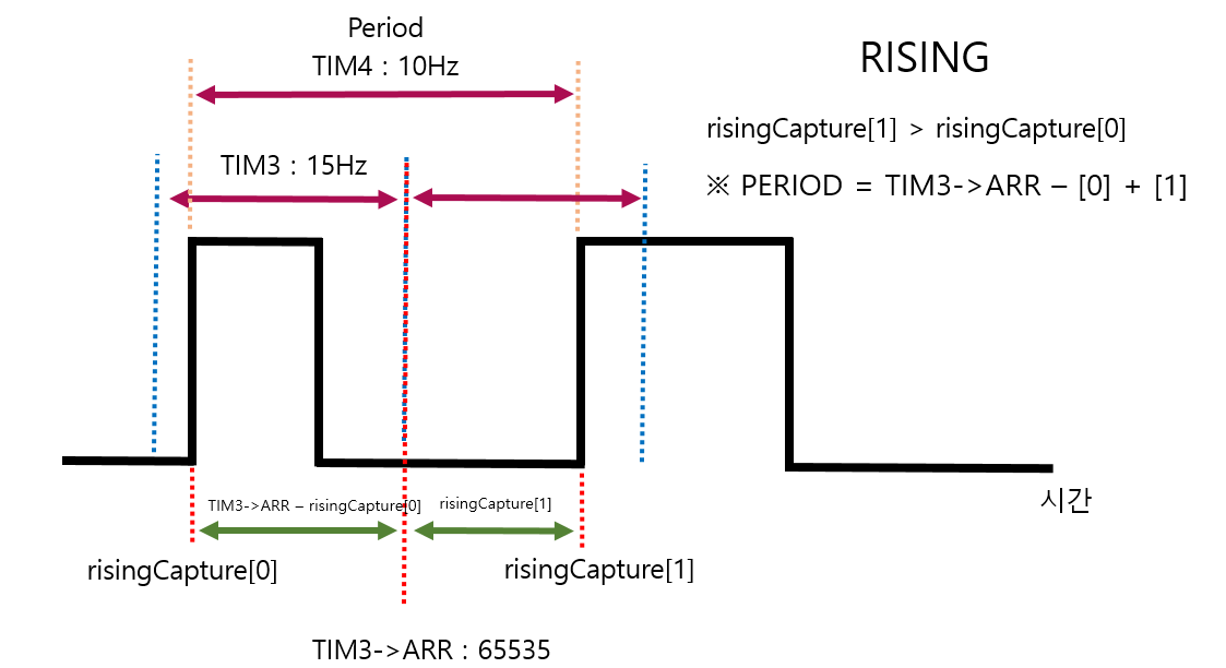
青い点線はTIM 3の間隔です.
黄色の点線はTIM 4の間隔です.
最初のif文では、タイマ3号のchannel 1がRisingを認識するとアクティブになります.
if(htim->Instance == TIM3 && htim->Channel == HAL_TIM_ACTIVE_CHANNEL_1)period += TIM3->ARR; // 65535 + 34000 => sonar PSC 150 rising PSC 90freq = (HAL_RCC_GetPCLK1Freq()*2)/(htim3.Instance->PSC + 1); // (45MHz*2) / 90 = 1MHz = 1,000,000 Hz
freq = freq/period;FALLING Edge
/* Falling */
	if(htim->Instance == TIM3 && htim->Channel == HAL_TIM_ACTIVE_CHANNEL_2)
	{
    	// Falling CCR 값 읽어오기
		fallingCapture[fallingCNT] = HAL_TIM_ReadCapturedValue(htim, TIM_CHANNEL_2);
		if(fallingCNT == 1){
			fallingCNT = 0;
		}else{
			fallingCNT = 1;
		}

		if(fallingCapture[0] >= risingCapture[0] && fallingCapture[0] <= risingCapture[1])
		{
			width = fallingCapture[0] - risingCapture[0];

		}
		else if(fallingCapture[1] >= risingCapture[0] && fallingCapture[1] <= risingCapture[1])
		{
			width = fallingCapture[1] - risingCapture[0];
		}
		GPIOB->ODR &= ~LD1_Pin;
		GPIOB->ODR |= LD2_Pin;

		distance = width / 58;
		if(distance > 400) distance = 400;

		duty = width * 100/period;

}fallingCapture[fallingCNT] = HAL_TIM_ReadCapturedValue(htim, TIM_CHANNEL_2);よく見るとrisingCapture[0]とrisingCapture[1]は変わっていません.
fallingCapture[0]とfallingCapture[1]のみが変更された.
要するに、最初のrippingを検出し、fallが0なのか1なのかを検出します.
if(fallingCapture[0] >= risingCapture[0] && fallingCapture[0] <= risingCapture[1])
{
	width = fallingCapture[0] - risingCapture[0];
}
else if(fallingCapture[1] >= risingCapture[0] && fallingCapture[1] <= risingCapture[1])
{
	width = fallingCapture[1] - risingCapture[0];
}
Full Code
/* USER CODE END Header */
/* Includes ------------------------------------------------------------------*/
#include "main.h"
#include "tim.h"
#include "usart.h"
#include "gpio.h"

/* Private includes ----------------------------------------------------------*/
/* USER CODE BEGIN Includes */
#include "stdio.h"		// printf
#include "stdbool.h"	// true, false
/* USER CODE END Includes */

/* Private typedef -----------------------------------------------------------*/
/* USER CODE BEGIN PTD */

/* USER CODE END PTD */

/* Private define ------------------------------------------------------------*/
/* USER CODE BEGIN PD */
/* USER CODE END PD */

/* Private macro -------------------------------------------------------------*/
/* USER CODE BEGIN PM */

/* USER CODE END PM */

/* Private variables ---------------------------------------------------------*/

/* USER CODE BEGIN PV */
volatile uint16_t risingCapture[2];
volatile uint16_t fallingCapture[2];
uint8_t risingCNT = 0;
uint8_t fallingCNT = 0;
uint32_t period, freq, duty;
uint16_t width, distance;

// Printf 사용을 위한 더미 파일
struct __FILE {
    int dummy;
};
FILE __stdout;

/* USER CODE END PV */

/* Private function prototypes -----------------------------------------------*/
void SystemClock_Config(void);
/* USER CODE BEGIN PFP */

int fputc(int ch, FILE *f)
{
  HAL_UART_Transmit(&huart3, (uint8_t *)&ch, 1, 0xFFFF);

  return ch;
}
/* 마이크로세컨드 함수 선언 */
uint32_t DWT_Delay_Init(void);
void DWT_Delay_us(volatile uint32_t microseconds);
void TriggerEnable(void);

/* USER CODE END PFP */

/* Private user code ---------------------------------------------------------*/
/* USER CODE BEGIN 0 */

/* USER CODE END 0 */

/**
  * @brief  The application entry point.
  * @retval int
  */
int main(void)
{
  /* USER CODE BEGIN 1 */

  /* USER CODE END 1 */

  /* MCU Configuration--------------------------------------------------------*/

  /* Reset of all peripherals, Initializes the Flash interface and the Systick. */
  HAL_Init();

  /* USER CODE BEGIN Init */

  /* USER CODE END Init */

  /* Configure the system clock */
  SystemClock_Config();

  /* USER CODE BEGIN SysInit */

  /* USER CODE END SysInit */

  /* Initialize all configured peripherals */
  MX_GPIO_Init();
  MX_TIM3_Init();
  MX_TIM4_Init();
  MX_USART3_UART_Init();
  /* USER CODE BEGIN 2 */
	// timer, channel, array, quantity
	DWT_Delay_Init();
	// HAL_TIM_PeriodElapsedCallback
	HAL_TIM_Base_Start_IT(&htim4);

	// HAL_TIM_OC_DelayElapsedCallback
  	HAL_TIM_OC_Start_IT(&htim4, TIM_CHANNEL_1);		// create Sonar

	// HAL_TIM_IC_CaptureCallback
	HAL_TIM_IC_Start_IT(&htim3, TIM_CHANNEL_1);		// rising
	HAL_TIM_IC_Start_IT(&htim3, TIM_CHANNEL_2);		// falling

	printf("start the program\r\n");
	HAL_Delay(2000);
  /* USER CODE END 2 */

  /* Infinite loop */
  /* USER CODE BEGIN WHILE */
  while (1)
  {

		HAL_Delay(100);

		printf("[%5d, %5d]-%5d = %5d => Distance %4d cm| period : %6d | freq : %3d Hz| duty : %d %%\r\n", risingCapture[0], risingCapture[1], fallingCapture[0], width ,distance, period , freq, duty);

    /* USER CODE END WHILE */

    /* USER CODE BEGIN 3 */
  }
  /* USER CODE END 3 */
}

/**
  * @brief System Clock Configuration
  * @retval None
  */
void SystemClock_Config(void)
{
  RCC_OscInitTypeDef RCC_OscInitStruct = {0};
  RCC_ClkInitTypeDef RCC_ClkInitStruct = {0};

  /** Configure the main internal regulator output voltage
  */
  __HAL_RCC_PWR_CLK_ENABLE();
  __HAL_PWR_VOLTAGESCALING_CONFIG(PWR_REGULATOR_VOLTAGE_SCALE1);
  /** Initializes the RCC Oscillators according to the specified parameters
  * in the RCC_OscInitTypeDef structure.
  */
  RCC_OscInitStruct.OscillatorType = RCC_OSCILLATORTYPE_HSE;
  RCC_OscInitStruct.HSEState = RCC_HSE_BYPASS;
  RCC_OscInitStruct.PLL.PLLState = RCC_PLL_ON;
  RCC_OscInitStruct.PLL.PLLSource = RCC_PLLSOURCE_HSE;
  RCC_OscInitStruct.PLL.PLLM = 4;
  RCC_OscInitStruct.PLL.PLLN = 180;
  RCC_OscInitStruct.PLL.PLLP = RCC_PLLP_DIV2;
  RCC_OscInitStruct.PLL.PLLQ = 4;
  if (HAL_RCC_OscConfig(&RCC_OscInitStruct) != HAL_OK)
  {
    Error_Handler();
  }
  /** Activate the Over-Drive mode
  */
  if (HAL_PWREx_EnableOverDrive() != HAL_OK)
  {
    Error_Handler();
  }
  /** Initializes the CPU, AHB and APB buses clocks
  */
  RCC_ClkInitStruct.ClockType = RCC_CLOCKTYPE_HCLK|RCC_CLOCKTYPE_SYSCLK
                              |RCC_CLOCKTYPE_PCLK1|RCC_CLOCKTYPE_PCLK2;
  RCC_ClkInitStruct.SYSCLKSource = RCC_SYSCLKSOURCE_PLLCLK;
  RCC_ClkInitStruct.AHBCLKDivider = RCC_SYSCLK_DIV1;
  RCC_ClkInitStruct.APB1CLKDivider = RCC_HCLK_DIV4;
  RCC_ClkInitStruct.APB2CLKDivider = RCC_HCLK_DIV2;

  if (HAL_RCC_ClockConfig(&RCC_ClkInitStruct, FLASH_LATENCY_5) != HAL_OK)
  {
    Error_Handler();
  }
}

/* USER CODE BEGIN 4 */


/* Trigger 핀 활성화 */
void HAL_TIM_PeriodElapsedCallback(TIM_HandleTypeDef *htim)
{
	if(htim->Instance == TIM4)
	{
		GPIOB->ODR |= 0x01 << 6;  // PB 6 SET
	}
}

/* Trigger 핀 비활성화 */
void HAL_TIM_OC_DelayElapsedCallback(TIM_HandleTypeDef *htim)
{
	if(htim->Instance == TIM4)
	{
		GPIOB->ODR &= ~(0x01 << 6);	// PB 6	RESET, Pulse
	}
}


/* Input Capture 시 활성화 */
void HAL_TIM_IC_CaptureCallback(TIM_HandleTypeDef *htim)
{

	/* Rising */
	if(htim->Instance == TIM3 && htim->Channel == HAL_TIM_ACTIVE_CHANNEL_1)
	{
		// Rising CCR 값 읽어오기
		risingCapture[risingCNT] = HAL_TIM_ReadCapturedValue(htim, TIM_CHANNEL_1);
		if(risingCNT == 1){
			risingCNT = 0;
			if(risingCapture[0] > risingCapture[1])
			{
				period = TIM3->ARR - risingCapture[0] + risingCapture[1];
                GPIOB->ODR |= LD3_Pin;
			}
			else
			{
				period = risingCapture[1] - risingCapture[0];
			}

			period += TIM3->ARR;	// 65535 + 34000 =>  sonar PSC 150 rising PSC 90
		}
		else
		{
			risingCNT = 1;
			GPIOB->ODR &= ~LD3_Pin;
		}
		GPIOB->ODR |= LD1_Pin;
		GPIOB->ODR &= ~LD2_Pin;

		freq = (HAL_RCC_GetPCLK1Freq()*2)/(htim3.Instance->PSC + 1);	// (45MHz*2) / 90 = 1MHz = 1,000,000 Hz
		freq = freq/period;


	}

	/* Falling */
	if(htim->Instance == TIM3 && htim->Channel == HAL_TIM_ACTIVE_CHANNEL_2)
	{
    	// Falling CCR 값 읽어오기
		fallingCapture[fallingCNT] = HAL_TIM_ReadCapturedValue(htim, TIM_CHANNEL_2);
		if(fallingCNT == 1){
			fallingCNT = 0;
		}else{
			fallingCNT = 1;
		}

		if(fallingCapture[0] >= risingCapture[0] && fallingCapture[0] <= risingCapture[1])
		{
			width = fallingCapture[0] - risingCapture[0];

		}
		else if(fallingCapture[1] >= risingCapture[0] && fallingCapture[1] <= risingCapture[1])
		{
			width = fallingCapture[1] - risingCapture[0];
		}
		GPIOB->ODR &= ~LD1_Pin;
		GPIOB->ODR |= LD2_Pin;

		distance = width / 58;
		if(distance > 400) distance = 400;

		duty = width * 100/period;

	}
}


uint32_t DWT_Delay_Init(void)
{
  /* Disable TRC */
  CoreDebug->DEMCR &= ~CoreDebug_DEMCR_TRCENA_Msk; // ~0x01000000;
  /* Enable TRC */
  CoreDebug->DEMCR |=  CoreDebug_DEMCR_TRCENA_Msk; // 0x01000000;

  /* Disable clock cycle counter */
  DWT->CTRL &= ~DWT_CTRL_CYCCNTENA_Msk; //~0x00000001;
  /* Enable  clock cycle counter */
  DWT->CTRL |=  DWT_CTRL_CYCCNTENA_Msk; //0x00000001;

  /* Reset the clock cycle counter value */
  DWT->CYCCNT = 0;

     /* 3 NO OPERATION instructions */
     __ASM volatile ("NOP");
     __ASM volatile ("NOP");
  __ASM volatile ("NOP");

  /* Check if clock cycle counter has started */
     if(DWT->CYCCNT)
     {
       return 0; /*clock cycle counter started*/
     }
     else
  {
    return 1; /*clock cycle counter not started*/
  }
}

void DWT_Delay_us(volatile uint32_t microseconds)
{
  uint32_t clk_cycle_start = DWT->CYCCNT;

  /* Go to number of cycles for system */
  microseconds *= (HAL_RCC_GetHCLKFreq() / 1000000);

  /* Delay till end */
  while ((DWT->CYCCNT - clk_cycle_start) < microseconds);
}

void TriggerEnable(void)
{
	GPIOB->ODR &= ~TRIGGER_Pin;	// initialize
	DWT_Delay_us(2);
	GPIOB->ODR |= TRIGGER_Pin;	// Trigger signal
	DWT_Delay_us(11);
	GPIOB->ODR &= ~TRIGGER_Pin;	// shut down
}

/* USER CODE END 4 */

/**
  * @brief  This function is executed in case of error occurrence.
  * @retval None
  */
void Error_Handler(void)
{
  /* USER CODE BEGIN Error_Handler_Debug */
  /* User can add his own implementation to report the HAL error return state */
  __disable_irq();
  while (1)
  {
  }
  /* USER CODE END Error_Handler_Debug */
}

#ifdef  USE_FULL_ASSERT
/**
  * @brief  Reports the name of the source file and the source line number
  *         where the assert_param error has occurred.
  * @param  file: pointer to the source file name
  * @param  line: assert_param error line source number
  * @retval None
  */
void assert_failed(uint8_t *file, uint32_t line)
{
  /* USER CODE BEGIN 6 */
  /* User can add his own implementation to report the file name and line number,
     ex: printf("Wrong parameters value: file %s on line %d\r\n", file, line) */
  /* USER CODE END 6 */
}
#endif /* USE_FULL_ASSERT */
Reference
この問題について(STM 32 Input Capture(超音波センサ)を使用), 我々は、より多くの情報をここで見つけました https://velog.io/@lcooldong/STM32-Input-Capture-사용-초음파-센서テキストは自由に共有またはコピーできます。ただし、このドキュメントのURLは参考URLとして残しておいてください。
Collection and Share based on the CC Protocol